www.kfuenf.org
Home
Kawai K5 LCD Backlight Repair Guide |

|
Kawai K5
K5 Howto
Tech LCD Help
More Tech Help
Free Librarian
Patches Library
Misc Downloads
Kawai K5 Links
MIDI Chart
Other Infos
Java/Linux Dev.
MidiDeviceProvider
 email direct
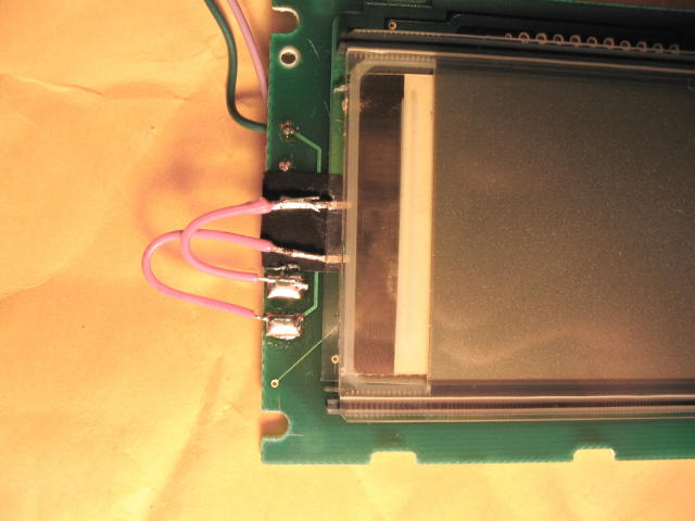
deutsch
sprachig
External Links:
Facebook K5 Group
Kawai Germany Forum
KAWAI US
Manuals & Patches
vintagesynth
sonicstate
kawai zone
Times go by and for highly improved technicans with huge skills in electronics the following may be interesting:
(Remark from Klaus Tzieply: i did not tried this.)
https://www.synth-parts.com - Site for complete new displays
-- WARNING! -- All notices and guides are only for experienced technicians, if you are in doubt, please do not do something that can damage your Kawai K5, read the notes on the bottom of this site. For this excellent article, all credits go to Harris Punyon(plays a K5 live on stage)!
How to replace the Backlight of a Kawai K5 by Harris Punyon.
By:  Harris Punyon (hpunyon@aol.com) 19'August 2003.

I've owned my K5 since it was new (15 years) and it's only given me two problems.

1) Dimming of the backlight.
2) Failing "tact" switches (Bank and Patch change).

Today I will document backlight replacement.

Background:
I discovered www.kfuenf.org (and
 www.backlights.co.uk) on 07'Aug and immediately ordered a blue backlight.
The cost was 34.99 $US. I paid using PayPal and my credit card was charged on 08'August.
On 16'Aug a plain brown envelope arrived with the backlight protected in folded cardboard inside.
(additional remark from Klaus at kfuenf.org: There is a worldwide supplier in Germany that are shipping worldwide:
Germany - with english language section: www.midi-rakete.de - German Company for new Backlights
There is a message with the following text:
Unlike the UK backlights that you have in your instructions, our backlights have the contacts
in the correct place (just like the original backlights from the original manufacturer)so no
messy jumper wire is required to connect the backlight to the contact pads on the display.
The 'messy jumper' is described in section (20) below - additional remark end.)
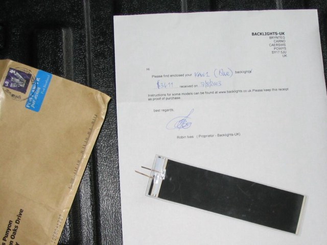
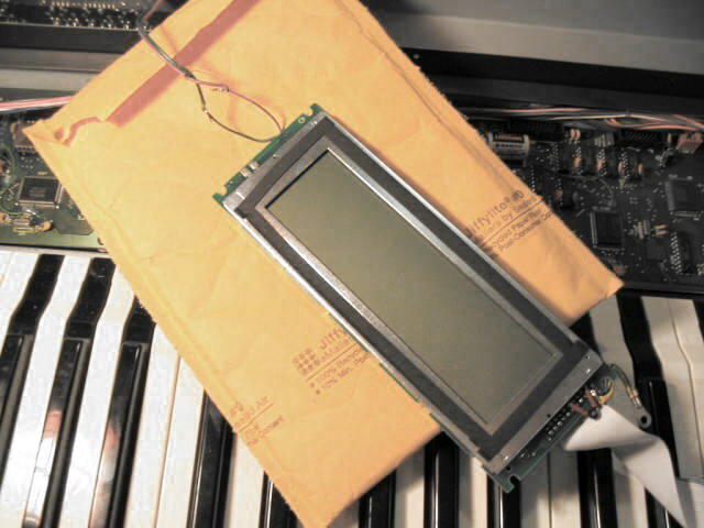
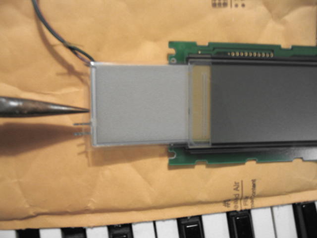
The replacement backlight is a flexible panel similar to paper between two peel and stick laminating
sheets.
There are two flat metal contacts on the short edge.
The light colored face emits light when installed in the K5.


Here's what it looks like:
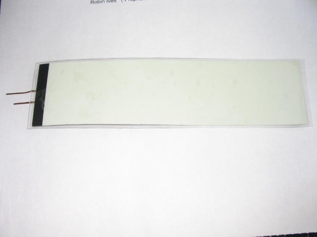
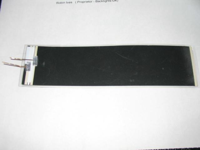
And the rear view:
Installation Procedure:

(Total elapsed time was about two hours.)

Getting Ready:

You must be competent with mechanical disassembly/reassembly
as well as with soldering (and desoldering) to perform the procedure below.
You will need the following tools and materials to replace your K5 backlight
with a backlight replacement from
www.backlights.co.uk:
o  Phillips screwdriver
o  Soldering iron (low wattage, mine is a Weller 25 Watt).
o  Solder
o  Desoldering braid
o  Electrical tape
o  Scissors
o  Long nosed pliers
o  Miniature 1/32" (8mm) flat screwdriver (smallest in the "jewelers" set)
o  Patience and a steady hand.

!!! POWER DOWN THE K5 AND REMOVE THE POWER CORD FROM THE UNIT !!!

(1)  Remove four phillips head screws found on the left and right edges near the top (2 left, 2 right).
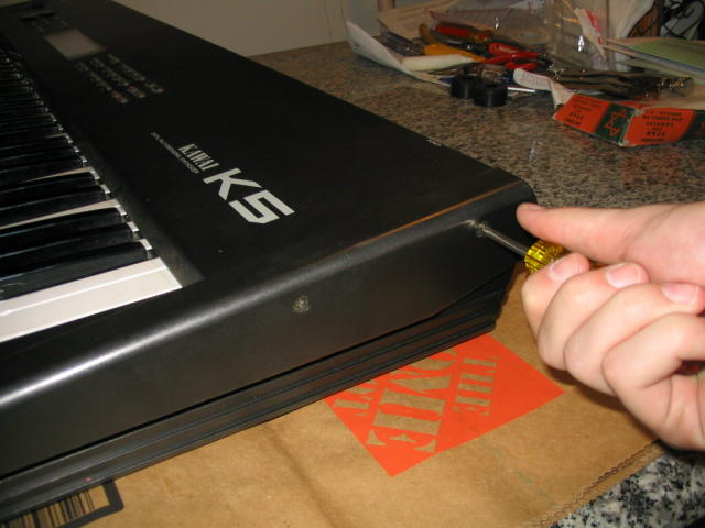
(2)  Lift the K5 control panel slowly from the rear of the keyboard.
     It will swivel up on it's hinge and sit upright.
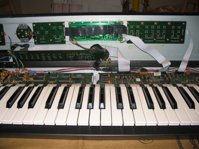
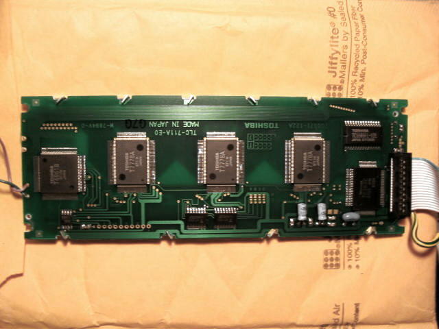
At this point, lay some paper or cloth over the keyboard to avoid damage.

(3)  There are green cards mounted on the control panel, the LCD card (Toshiba) is in the center.
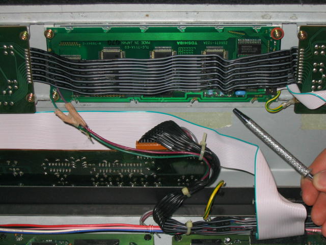
(4) As you can see, the LCD card is block by a black ribbon cable, which is soldered to the cards on
either side. We will remove the Bank/Patch select switch card (on the right, marked "M1-006") to
gain access to the LCD card.
o Follow the grey ribbon cable attached to the right side of the Bank/Patch select card to the main
board below, and disconnect.
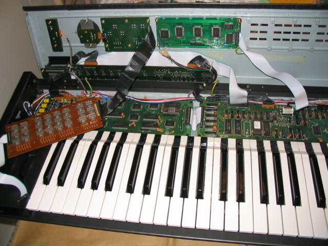
o Remove the 10 screws that secure the Bank/Patch select card and lay the card aside to the left.
Note: The lower left screw also secures the green ground lug for the LCD card.
IMPORTANT: Some screws have insulating washers (brown) and these MUST be replaced in the SAME POSITION
to avoid electrical shorts, which can RUIN YOUR K5.
!!! DURING THE NEXT STEPS, YOU WILL HANDLE THE LCD CARD.  DO SO VERY GENTLY.
    DO NOT DAMAGE THE GLASS OR DISTURB THE LCD ASSEMBLY UNDERNEATH.
    DO NOT DISASSEMBLE THE LCD OTHER THAN AS DIRECTED BELOW.
    IT WILL NOT SURVIVE !!!

(5)  Remove the four screws that secure the LCD card and lay the card down face up.
(6) Turn the LCD card over (glass down, BE CAREFUL not to damage or scratch the glass).
(7)  Note the 12 tabs that secure the aluminum LCD frame to the card.
     GENLTLY straighten these tabs, GENTLY remove the LCD frame, and put it aside for later.
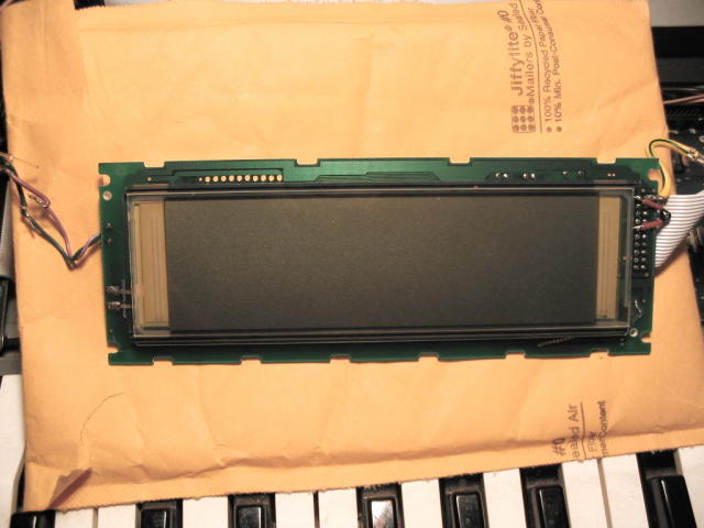
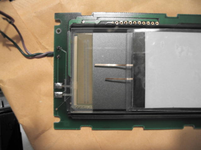
(8) Here's the LCD, face up, with the aluminum frame removed.
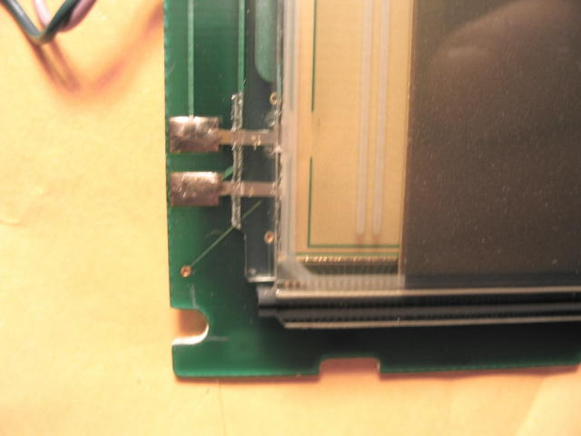
(9)  In the lower left corner, you can see the old backlight (encased in vinyl) with the two soldered
     connections.
(10) Note how the replacement backlight connections DO NOT LINE UP with the connection points on the
     LCD card.
(11) Desolder and loosen the two soldered connections:

o  First, add a bit of solder, this helps the desoldering braid work.
o  Remove as much solder as possible using desoldering braid.  Do not burn the board.
o  Once most of the solder is removed, detach the old backlight connection wires
   by gently inserting a SMALL screwdriver behind the backlight plastic.
   Then apply heat to the connections while lifting gently with the screwdriver
   until the wire lifts off the board.
   DO NOT USE FORCE.
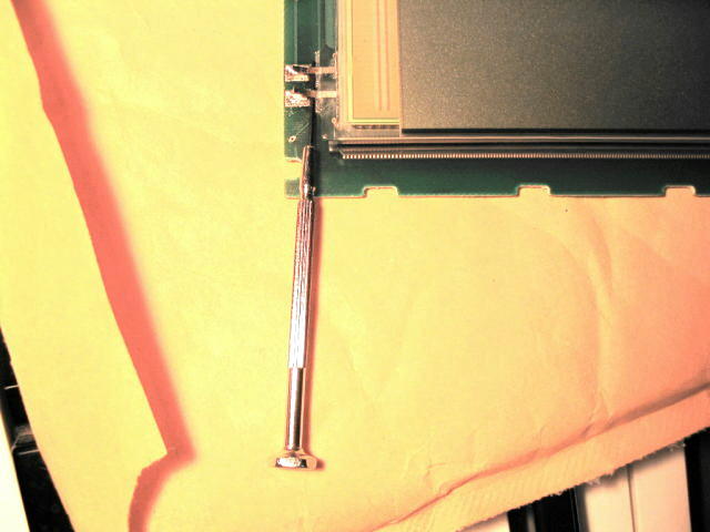
(12) When the wires are loose, use a long nosed pliers to slide the old backlight out.
     You will need to bend GENTLY upwards to clear the two solder connections.
(13) Apply a small piece of black electrical tape to the card as shown to protect the card.
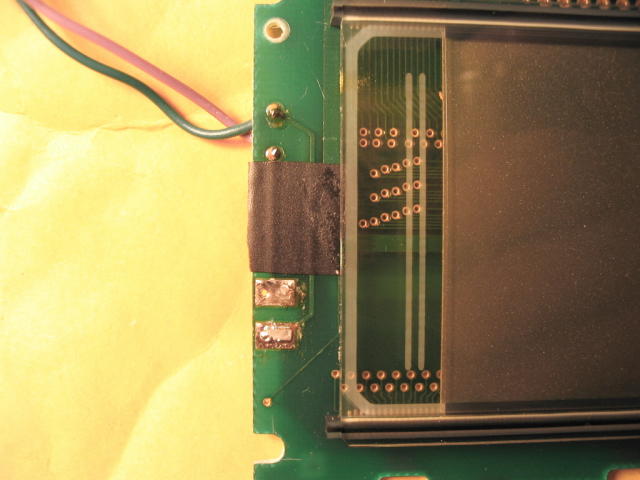
(14) GENTLY slide the new backlight, black side DOWN, into the LCD assembly.

(15) Cut the connection wires even with the edge of the card.

(16) Tin the ends.

(17) Cut two 2" (5cm) lengths of stranded connection wire, strip 1/4" (60mm) from each end, and tin.

(18) Solder the two connection wires to the backlight connection wires.

(19) Loop the connection wires back and solder to the LCD connection points.

ENSURE THAT THE UPPER BACKLIGHT WIRE CONNECTS TO THE UPPER LCD CONNECTION POINT (see diagram).
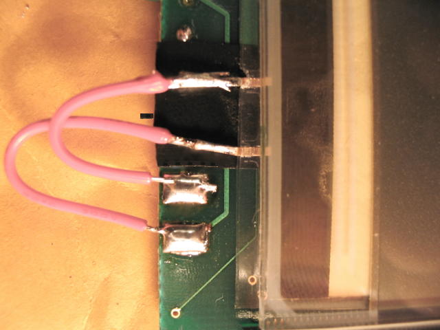
Here's a zoomed view.
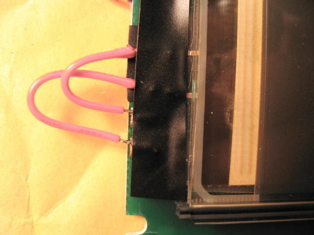
(20) Cut and apply a piece of black electrical tape to cover the connections and secure the backlight.
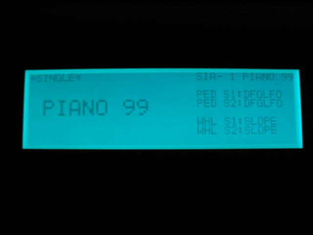
(21) Reattach the aluminum LCD frame; gently twist the 12 aluminum tabs to secure.

(22) Remount the LCD card with four screws.

(23) Remount the Bank/Patch Select card with ten screws.

REMEMBER TO:

o  Return the screws with the insulating washers to their original positions.
o  Attach the GROUND jumper from the LCD card to the lower left screw.
o  Attach the grey ribbon cable to the main card below.  It is keyed, so observe the insertion direction.

(24) Gently lower the control panel and reattach with the four side screws.

(25) Apply power and enjoy.
Additional comment from Klaus Tzieply (klaus at kfuenf dot org):
YOU ARE USING THE REPLACEMENT GUIDE ON YOUR OWN RISK!
IF SOMETHING IS GOING WRONG AND YOUR KAWAI K5 IS HARMED OR DAMAGED
THE PEOPLE OF WWW.KFUENF.ORG AND THE AUTHORS OF THE GUIDES AND ARTICLES
WILL NOT BE LIABLE FOR DATA LOSS, DAMAGES, LOSS OF PROFITS OR ANY KIND OF LOSS
WHILE USING OR MISUSING THIS GUIDE.
NO WARRANTY OF ANY KIND IS EXPRESSED OR IMPLIED.
All links on this guide site are not for advertising, they are only linked here for helping K5 owners.
 Back to Top